Chilled water thermal energy storage system utilizes off-peak electricity, which is usually cheaper than on-peak, electricity to cool off water. The system utilizes only the sensible heat of water for cooling energy storage in a chilled water storage tank and discharges the stored coldness for air-conditioning in on-peak time. This operation scheme will reduce the total energy consumption and operation cost.
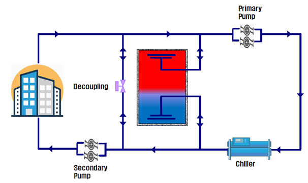
CW TES has long history of installation and widely applied around world including U.S.A., Japan, Korea and Middle East Asia.
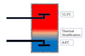
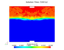
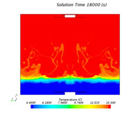
The key technology of CW TES system is the diffuser design which ensures thermal stratification of chilled water and warm water by density difference. FT Energy`s Technology is the state-of-the-art technology which is recommended at ASHRAE's design guideline.

ISO 9001

ISO 14001
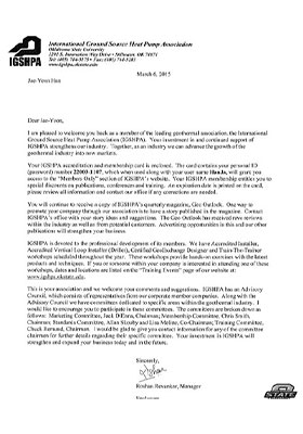
IGSHPA Member (Oklahoma State University)
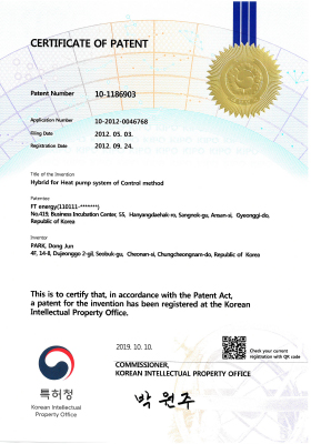
Certificate of Patent
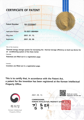
Certificate of Patent
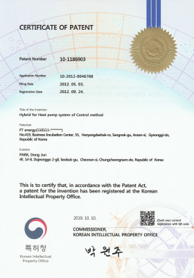
Registration of Patent

IDEA Certificate
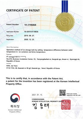
Certificate of Patent
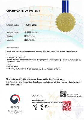
Certificate of Patent
FT Energy implemented an Uninterruptible Chilled Water Supply (UCS) tank that enabled a high density data center to survive a power outage without costly thermal damage to servers. The system, based on auxiliary chilled water storage tanks, kept the data center cool when an outage caused the chillers to shut down.
In data centers with high power and heat densities, a power sag or outage can cause rapid temperature increases. This is because cooling systems temporarily shut down, while servers keep producing heat because they are on an uninterruptible power supply (UPS).
To overcome this problem, FT Energy implemented an Uninterruptible Chilled Water Supply Tank(UCS) at a large regional hub data center. The system, based on pressurized tanks containing chilled water operated successfully during an outage that lasted several hours.
When the chillers stopped working, the system added water from the tanks to the chilled water system to maintain cool data center temperatures.
Chilled water system pumps and air handler fans continued operating because they were on UPS and generator backup power.
Servers continued to operate for more than 15 minutes due to the light load on the data center at the time of the utility power outage.
The thermal reserve maintained cooling during this period and for long enough afterwards to allow dissipation of residual heat from the servers.
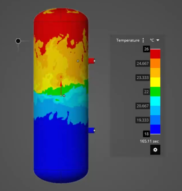
Vertical type
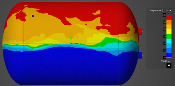
Horizontal type
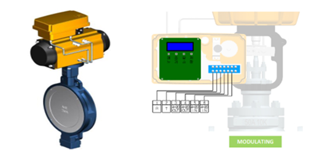
| BODY | ACTUATOR | ||
|---|---|---|---|
| Pressure | KS 10k/20k/40k | Power | AC 24 / AC 220V |
| Signal | 4~20 mA | ||
| Temperature | -20 ℃ ~ 220 ℃ | Speed | 0.44mm/s & 0.8mm/s |
| Speed control | Bidirectional speed control | ||
| Flow Media | Water, Oil, Gas, Steam | Duty Rating | 100% |
| Operating type | Single / Double acting | ||
| Assembly | Separation/Combination method | ||
| Applied Type | Globe, Butterfly | Local Switch | Auto/Manual and |
FT ENERGY TES SYSTEM/ DATA CENTER
Is a two-component, light weight, energy efficient insulation system that can be utilized in the form of prefabricated rigid board stock, spray pour of froth applied, depending on design and product requirements
The proper ratio of these raw materials cross linked together, provide an insulating material with a high strength to weight ratio, good thermal stability, low thermal conductivity with excellent adhesion to most substrate materials.
Since rigid polyurethane foam is 90 to 95% closed fine cell, it provides the lowest “K” and highest “R” factor, commercially available.
These advantages make polyurethane foam the most energy efficient and cost effective insulation material currently available.
Unlike the spray method, FT Energy uses the injection method to insulate. The advantages of the injection type compared to the general spray method are as follows.
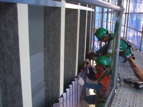
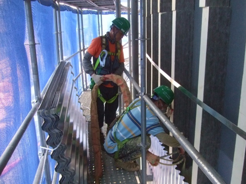
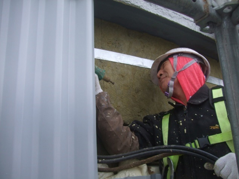
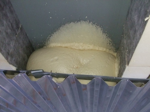
The best insulation efficient polyurethane foam is composed of independent closed cells filled with freon gas, thus, has lowest thermal conductivity among various other insulating materials which are being used for cold storage facilities.
| PROPERTIES | VALUE |
|---|---|
| DENSITY (g/cm3) | 0.025 ~ 0.050 |
| THERMAL CONDUCTIVITY (Kcal/mh℃) | 0.018 ~ 0.021 |
| COMPRESSIVE STRENGTH (Kg/cm2) | 1.5 ~ 4.5 |
| SERVICE TEMPERATURE (℃) | -170 ~ 100 |
| WATER ABSORPTION (%) | Less than 3% |
| CLOSED CELL CONTESTS (%) | 90 ~ 95 |
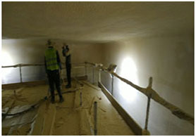
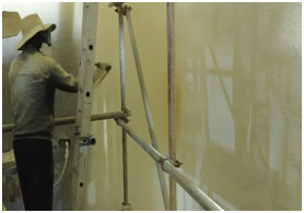
Tank bottom insulation
Tank Ceiling insulation
Tank Wall insulation
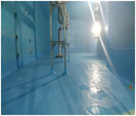
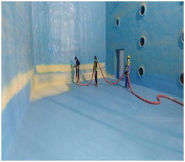
Tank bottom waterproofing
Tank Ceiling waterproofing
Tank Wall waterproofing
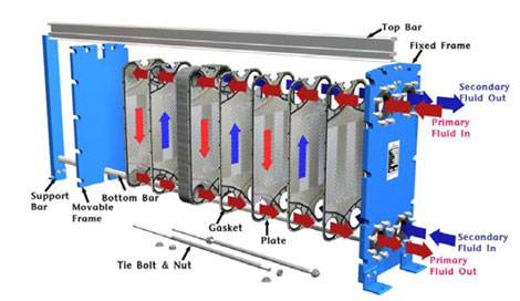
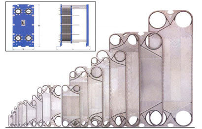
Plate Heat Exchanger(PHE) consists of corrugated thin heat plates, seal gaskets, top & bottom bar, frame and etc. The heat plates have high heat transfer coefficients by turbulent flow of the channel band. The gaskets forms the flow path of the primary and secondary fluids as well as sealing.
| Model | AREA m2 | Standard Nozzle Size | MAX Flow m3/hr | SIZE mm | |||
|---|---|---|---|---|---|---|---|
| W | H | L | |||||
| TX05 | 0.0152 | 3/4” (20A) | 4 | 128 | 270 | 70 ~ 320 | |
| TX07 | 0.034 | 1 1/2” (40A) | 12 | 192 | 466 | 330 ~ 510 | |
| TX3 | GD | 0.09 | 2 1/2” (65A) | 50 | 346 | 775 | 517 ~ 1680 |
| AN | 0.17 | 1145 | |||||
| AX | 0.25 | 1515 | |||||
| TX4 | GD | 0.101 | 4” (100A) | 120 | 495 | 874 | 780 ~ 1780 |
| AP | 0.228 | 1151 | |||||
| AN | 0.348 | 1428 | |||||
| AX | 0.467 | 1705 | |||||
| TX8 | GD | 0.37 | 8” (200A) | 550 | 740 | 1459 | 1390 ~ 1780 |
| AN | 0.68 | 1944 | |||||
| TX9 | GD | 0.27 | 8” (200A) | 550 | 740 | 1297 | 1150 ~ 2770 |
| AP | 0.47 | 1620 | |||||
| AN | 0.68 | 1944 | |||||
| AX | 0.89 | 2267 | |||||
| TX14 | GD | 0.84 | 12” (300A) | 1200 | 1012 | 1922 | 1360 ~ 5060 |
| AP | 1.28 | 2338 | |||||
| AN | 1.62 | 2754 | |||||
| TX16 | AN | 3.06 | 18” (450A) | 2600 | 1400 | 3966 | 2130 ~ 5030 |
| TX20 | GD | 1.08 | 20” (500A) | 3500 | 1420 | 2488 | 2130 ~ 5030 |
| AP | 2.07 | 3226 | |||||
| PLATE MATERIAL | Stainless Steel, SMO254, SLX904, Titanium, Titanium-Paladium, Nickel, Nickel alloy, Hastelloy-B, Hastelloy-C |
|---|---|
| GASKET MATERIAL | NBR, EPDM, CR, Butyl, Viton, Teflon R, Silicon, Reflon R |
| FRAME MATERIAL | Carbon Steel, Stainless Steel, Stainless Steel Lining |
